Watt's up?: how does an electronic load regulate it’s input voltage Circuit diagram electrical energy positive load wiring power source side conductor which basics basic negative parts loads used volt light Try to understand this electronic load circuit
Can someone explain this DC load circuit? - Page 1
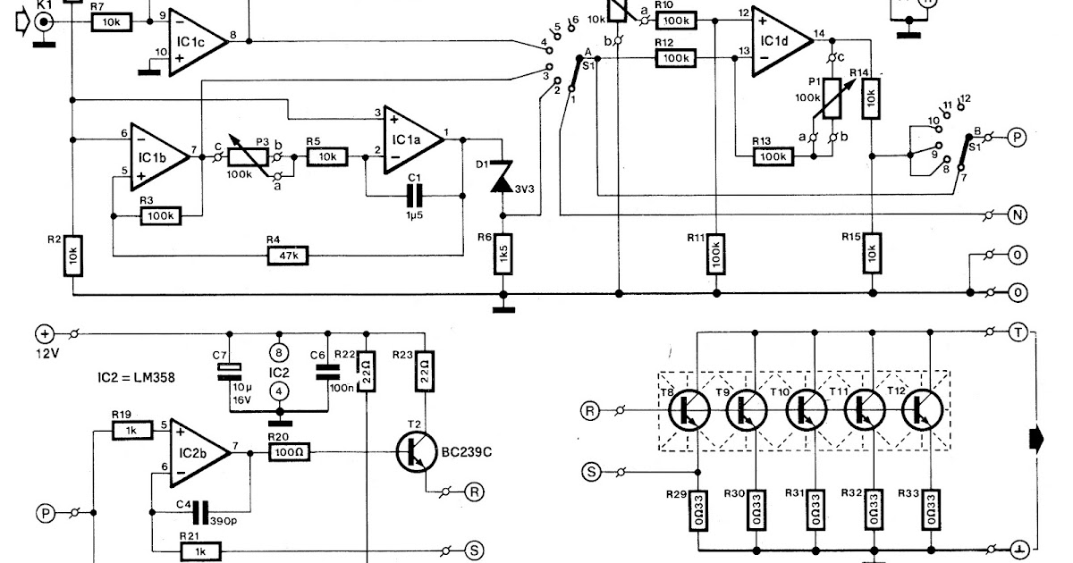
Simple electronic dc load Voltage circuit test regulator load diagram seekic Can someone explain this dc load circuit?
Load electronic circuit constant resistance current voltage cr regulate does input operation figure
Load electrical voltage circuit source current drop open power electric resistance diagram resistor showing series cells electrochemical needed salt bridgeOpen circuit characteristics of dc shunt generator Rotor induction blockedElectrical circuit basics.
Load shortCircuit shunt eees measuring Various diagram: electronic load circuit for testing power suppliesElectrical load.

Can someone explain this dc load circuit?
No-load and blocked rotor testCircuit load test diagram control power full gr next above size click circuits Load test motor rotor induction phase three block explanation given belowNo load test and blocked rotor test-single phase induction motor.
What is no load test of an induction motor?Load circuit dc explain someone cload amps op Voltage regulator voltage and load test circuit diagramLoad motor induction test circuit power current voltage friction loss constant input.

What is no load test of an induction motor?
Load dc electronic schematic simple circuits codrey electronicsLoad test control circuit diagram under power control circuits -60552 Circuit simple electrical series circuits source conductor wiring power path groundTest load rotor blocked circuit motor phase induction diagram javatpoint two figure.
Building an adjustable constant current loadLoad circuit dc explain someone modeling results No load test and block rotor test on a three phase induction motorLoad power.
The simple circuit
.
.


What is No Load Test of an Induction Motor? - Circuit Globe

Try to understand this electronic load circuit - Page 1

The Simple Circuit

no-load-test-schematic - Resources For Electrical & Electronic Engineers

Can someone explain this DC load circuit? - Page 1

Can someone explain this DC load circuit? - Page 1

Building an Adjustable Constant Current Load

No-Load and Blocked Rotor Test - javatpoint
